Structural Engineering Research Lab
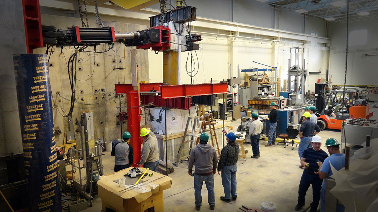
This leading-edge testing facility, housed in Butler-Carlton Civil Engineering Hall, opens new doors to projects, funding sources and hands-on learning for students. It contains state-of-the-art equipment and is suitable for testing large-scale components and systems.
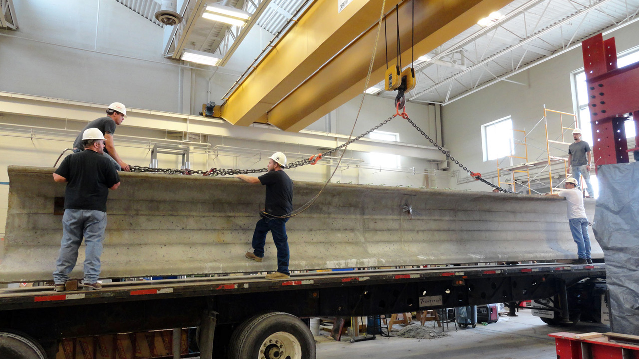
The High-bay Structural Engineering Research Laboratory, as it's called, was completed in 2003. The lab was built with easy access to two major streets on either side. It has 770 m2 of usable floor area for testing and evaluation of structural components and systems. The laboratory is approximately 35 m long, which is ideal for testing large- and full-scale structures. Inside the laboratory a 20-ton overhead crane was installed with a vertical clearance of 6 m.
The laboratory also has a bidirectional reaction wall 5.5 m in height. Outside the north entrance of the lab, a loading dock was built with an exterior crane of 20-ton capacity to load and unload large specimens. The High-bay Structures Lab also has a twin tunnel basement under the 258 m2 strong floor to facilitate anchorage of testing setups.
A materials laboratory is connected to the high-bay area that is accessible to prepare structural samples and related materials testing. And there is a machine shop to provide support for the fabrication of custom equipment and test specimens.
Equipment
MTS Large Scale Testing Equipment
Missouri S&T acquired research equipment capable of testing large-scale specimens under NSF Award CMS-0116273. This entire system was set in operation in the spring of 2003, and up-to-date testing has been successfully conducted on two 1:1.25 scale column-beam joint connection models and other large scale specimens. The testing equipment consisted of three hydraulic actuators with servo-controlled valves for pseudo-static testing. The three actuators consist of 2-MTS 490kN force capacity and a 510 mm stroke capacity, and 1-MTS 980kN force capacity and a 760 mm stroke capacity. In 2008, two additional actuators were added: 1-MTS 980 kN force capacity and a 760 mm stroke capacity, and 1-MTS 490 kN force capacity (fatigue rated) and a 510 mm stroke capacity. To complement this equipment, the following are also available; hydraulic service manifolds, one 350-litter/m hydraulic power pump, and one MTS-493.05 FlexTest GT electronic control system. In addition, assembly of a 128-channel high-capacity data acquisition system (DAS) was completed; the system can be expanded to 256-channels.
Existing research and educational equipment
Missouri S&T has a unidirectional shaking table (1.22 m x 2.14 m in size) that was built and installed by MTS Systems Corporation in Eden Prairie, Minn. This shaking table supports a maximum payload of 200 kN. Together with a small hydraulic actuator (± 38 mm stroke), the controller has been successfully employed to control a ¼ -scale building frame mounted on the shake table. In December 2013, the SERL lab acquired a new uniaxial earthquake simulator (shaking table). The earthquake simulator has a payload mass of 10,000 Kg, peak velocity of 1.2 m/sec, and peak acceleration of 24 m/sec2. The shaking table runs using a hydraulic linear actuator with a maximum static force of 250 kN. The actuator has a maximum stroke of +/- 25.4 mm. The simulator is controlled using advanced seismic simulation software that uses non-linear multi-pass on-line iterative technology for the most accurate test result. The simulator works on real time prerecorded acceleration time histories, sine sweep and sine control.
Computer Equipment
UNIX, Sun, SGI Indigo, HP, multi DAS and 20 PC Pentium stations are on hand and access to NCSA through Cornell Supercomputing is also available.
Missouri S&T Tornado Simulator
This facility can simulate the swirling tornadic wind. The generated tornadic wind flow can translate along a straight path using an overhead crane. The ground plane can raise and lower to achieve variations of floor height and observe changes associated with different tornado conditions. The scale of test model is roughly up to 1:150 for low rise buildings and up to 1:750 for high rise buildings. The swirling flow is generated through induced rotation from the angled vanes with the overall flow through the simulator being generated by the single central fan. The fan used in this facility generates 86,000 cubic feet per minute flow rate with a static pressure of 1.5 inches water. The flow through the tornado simulator follows a circulating pattern that recycles internal air without requiring a fresh air flow source. Air passes through a honeycomb section under the single central fan located in the inner chamber, via an updraft, and then proceeds into the vane section of the simulator. The air will then be forced into a rotation while being sent downward through the ducting towards the ground plane. This rotating air will then pass along the ground plane and feed back into the fan via the aforementioned updraft. The rotation imparted to the updraft will form the vortex of the tornado. The simulator ducting and vanes implement a smoothed radial design that allows for the air to pass through with minimal impediment.
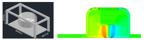
Pictured left is an overview of the tornado simulator and pictured right is a vertical plan of wind flow.
The lab also has a 44-kg Saraswati mechanical oscillator Type SEA-350. It is a compact, portable, easy to operate and lightweight machine used to induce controlled sinusoidal vibrations in structures, foundations and assemblies, etc. The oscillator can generate a maximum load of ± 5000 kg at 100 Hz with the maximum running speed of 6000 RPM. The unit is 317 x 226 x 170 mm in dimension.
There is a MTS880 universal testing machine (556-kN capacity and a ± 152.4 mm stroke), a Tinius-Olsen L120000 loading machine (600-kN capacity), and a Baldwin/Forney testing machine (2,224-kN capacity and a 254-mm stroke). Together with the MTS880 testing machine, the Camac crate with a Pentium II Computer can be used to record 64 channels of streaming data at the rate of 1.0 MHz. The laboratory is also equipped with a 32-channel data acquisition that is capable of streaming data at 100 kHz. It can be interfaced with the Tinius-Olsen and Baldwin loading machines. Two hydraulic actuators (2298-kN capacity and a ± 76 mm stroke, fatigue rated as 45 kN at the rate of 3 Hz) are also available for testing of small components. Both have been extensively used to test small-scale structural members. In addition, 6 loading jacks with range in capacity between 445-kN and 890-kN are on hand.
Resources
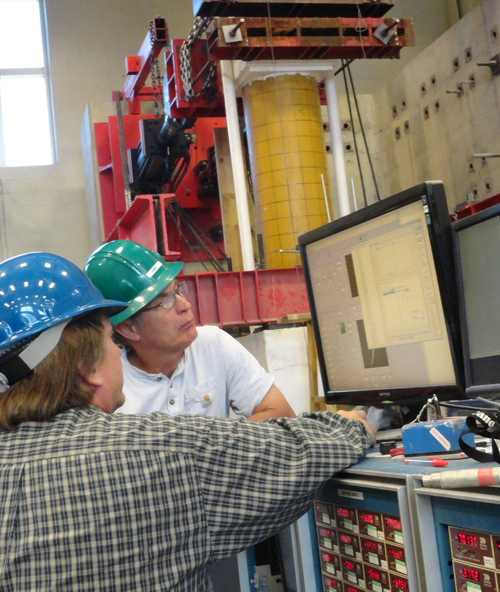
Brian Swift, an engineer II for the department, has a strong background in data acquisition, equipment installation, programming, operation and maintenance. Greg Leckrone, a research engineering technician, is in charge of the machine shop and Gary Abbott, a research engineering technician II, assists with the maintenance and repair of complex instruments and equipment in the lab.
Follow Civil, Architectural and Environmental Engineering